A professional injection molding supplier does more than run molding machines. It checks part geometry, resin behavior, tool construction, process settings, dimensional capability, inspection methods, and production capacity before volume production begins. A 1% scrap difference equals 10,000 parts on a 1-million-unit program, while cutting a 30-second molding cycle to 27 seconds raises theoretical output by about 11%. Tooling errors can be more expensive: changing a gate, cooling circuit, slider, or hardened steel insert after mold trials may require machining and another validation cycle. A capable supplier reduces those manufacturing variables before they reach regular production.
Injection molding starts with part geometry, not with machine settings. Wall thickness, draft, ribs, bosses, holes, snap features, undercuts, gate positions, weld lines, ejector locations, and cosmetic surfaces all affect whether a CAD model can be molded repeatedly. For many thermoplastics, keeping nominal wall thickness reasonably uniform helps reduce differential cooling; a section that is 3 mm thick can take considerably longer to cool than a nearby 1.5 mm section because cooling time does not increase in a simple one-to-one relationship with thickness.
That geometry review should happen before tool steel is machined. Many molded parts use draft angles around 0.5° to 2° or more, depending on depth, surface texture, resin, and ejection conditions. Deep textured walls often require more draft than smooth polished surfaces. Rib thickness is also commonly kept below the adjoining wall thickness to limit sink marks, although the exact ratio depends on polymer, geometry, and appearance requirements.
A drawing may describe the finished dimensions correctly while still leaving gate location, shrinkage, cooling balance, venting, and ejection unresolved.
Those unresolved points become tooling work. A production mold may contain hardened inserts, sliders, lifters, ejector systems, cooling channels, hot-runner components, replaceable wear parts, and several cavities. A four-cavity tool running a 24-second cycle can theoretically produce 600 parts per hour before downtime, rejects, mold service, color changes, and material interruptions are counted.
Cooling deserves particular attention because it often takes up a large share of the molding cycle. Cooling channels that sit too far from one side of the cavity can create different mold-surface temperatures across the part. That difference may show up as warpage, uneven shrinkage, or a longer cycle because the hottest section determines when the mold can open safely.
A supplier therefore has to evaluate mold construction against expected annual volume. A tool for 5,000 prototype parts does not need the same steel selection, automation, hot-runner configuration, wear resistance, and maintenance planning as a program expecting 500,000 parts per year. Tool price without expected service life gives an incomplete purchasing comparison.
Material behavior adds another set of variables. PP, ABS, PC, PA, POM, PBT, PMMA, TPE, TPU, PPS, and PC/ABS blends do not process at the same temperatures or shrink at the same rate. Fillers change the picture again. A polymer containing 30% glass fiber can behave very differently from the unfilled grade in stiffness, flow, shrinkage direction, tool wear, and warpage.
Moisture control is especially important for hygroscopic engineering plastics. Polyamide, polycarbonate, PET, PBT, and several other resins may require controlled drying before molding, with drying conditions taken from the resin manufacturer's technical data rather than guessed on the shop floor. Excess moisture can contribute to hydrolytic degradation, surface defects, reduced molecular weight, and weaker mechanical performance.
The resin trade name alone is not enough. Grade, filler percentage, flame rating, color system, moisture condition, regrind allowance, and approved supplier all affect production.
Material traceability matters more as annual volume rises. If a plant produces 250,000 components from several resin lots during a year, lot identification makes it easier to isolate affected inventory when a material certificate, color result, mechanical property, or molding condition needs review. Without lot records, a supplier may have to inspect a much larger quantity than the batch actually involved.
After resin and tooling are defined, processing determines whether the same mold produces the same part hour after hour. Injection speed, melt temperature, mold temperature, transfer position, holding pressure, holding time, screw recovery, back pressure, cushion, cooling time, and clamp settings can all influence dimensions or appearance.
A stable process should use an approved operating window rather than one exact machine setting copied from a trial sheet. If acceptable parts are produced only at 95 MPa holding pressure but fail at 93 or 97 MPa, the process has little room for normal material and equipment variation. Process development should show which parameters have a meaningful effect on filling, packing, shrinkage, and part weight.
Part weight is often useful as a routine process indicator. If an approved component weighs 42.0 g and normal production remains within a narrow validated range, a sudden shift may point to material, cushion, packing, check-ring, or process changes. Weight cannot replace dimensional inspection, but it can identify process changes earlier than waiting for a finished lot to reach final inspection.
A high-output mold makes early detection more important. An eight-cavity mold with a 20-second cycle produces a theoretical 1,440 parts per hour. A problem left unnoticed for one four-hour period could affect up to 5,760 molded pieces before accounting for breaks or downtime. A 2% reject rate at 1 million annual units represents 20,000 rejected components.
That is why a Reliable injection molding partner should control production upstream instead of depending only on inspectors at the end of the line. First-piece approval, in-process checks, machine parameter records, cavity identification, material-lot records, scheduled inspections, and reaction limits provide more information than a final visual check alone.
Dimensional inspection needs the same level of planning. A plastic housing may have 50 drawing dimensions, but perhaps only 6 directly affect sealing, assembly, alignment, or mating hardware. Those 6 dimensions may need tighter sampling or dedicated gauges, while less important dimensions can follow a different inspection frequency.
Measurement equipment should match the feature. Calipers are useful for many general dimensions but are not the right instrument for every tight tolerance. CMMs, optical systems, pin gauges, thread gauges, height gauges, custom fixtures, force gauges, and vision equipment may be better for specific features. Measuring a ±0.03 mm feature with equipment that cannot reliably resolve the required difference gives little production control.
Capability data also adds context to a dimension report. Manufacturers often use Cp and Cpk studies to evaluate process spread and centering, with 1.33 frequently used as a customer or company capability target for stable production, although required limits vary by industry, drawing, and contract. The important point is that a few acceptable samples do not show how a process behaves across thousands of cycles.
Ten acceptable parts can prove that ten parts passed inspection. They cannot by themselves show that 100,000 future parts will remain inside tolerance.
For automotive work, customers may require systems aligned with IATF 16949:2016 and production approval documents such as control plans, process flow information, measurement records, and PPAP-related submissions. Medical-device programs may involve ISO 13485:2016 requirements, while general manufacturing suppliers often operate quality systems based on ISO 9001:2015. Certification alone does not prove that a specific molded part will be good, but documented systems make responsibilities, records, corrective work, and change control easier to audit.
Change control becomes important after production approval. Replacing a resin grade, moving a mold to another machine, changing a hot-runner component, repairing a cavity insert, or modifying a process setting can affect the part even if the CAD file remains unchanged. A supplier should know which changes require internal revalidation and which require customer approval before the next production lot.
Tool maintenance affects the same production history. Vents can become contaminated, ejector components can wear, slides need lubrication, cooling circuits can collect deposits, and parting surfaces can become damaged. A mold running a 30-second cycle completes about 120 cycles per hour; at 5,000 operating hours, that is roughly 600,000 cycles. Maintenance intervals therefore need to reflect actual mold construction, resin abrasiveness, cavity count, and operating history.
Fiber-filled materials can increase wear on gates, runners, screw components, and mold surfaces compared with many unfilled polymers. A supplier running glass-filled engineering plastics should inspect wear areas rather than waiting for flash, gate changes, dimensional drift, or surface defects to become visible in shipped parts.
Production planning also affects cost. A quotation based on 50,000 annual pieces may use a different cavity count, machine size, automation level, packaging method, and raw-material purchase volume than a quotation based on 1 million pieces. Comparing two suppliers requires confirming that both prices were calculated from the same annual volume, resin grade, inspection level, packaging specification, tool ownership terms, and secondary operations.
| Production item | Example production effect |
|---|---|
| 30 sec to 27 sec cycle | About 11% more theoretical hourly output |
| 1% scrap at 1,000,000 parts | 10,000 rejected parts |
| 8 cavities at 20 sec | 1,440 theoretical parts/hour |
| ±0.05 mm assembly feature | Requires suitable measurement capability |
| 30% glass-filled resin | Different shrinkage and wear behavior from unfilled resin |
| 600,000 mold cycles | Maintenance history becomes commercially relevant |
Secondary operations should be included in the same calculation. Threaded inserts, ultrasonic welding, pad printing, laser marking, heat staking, painting, adhesive bonding, machining, testing, and final assembly can add more process stages than molding itself. A $0.04 molding saving loses importance if a separate operation adds $0.12 in handling, freight, inspection, or rework.
Insert molding shows why coordination matters. A metal insert has to be held in position while molten polymer enters the cavity at pressure. Insert location, mold shutoff, thermal expansion, plastic flow, retention geometry, and operator or robotic placement can affect the finished part. A process producing 3,000 insert-molded pieces per shift needs a placement method that remains repeatable across thousands of loading cycles.
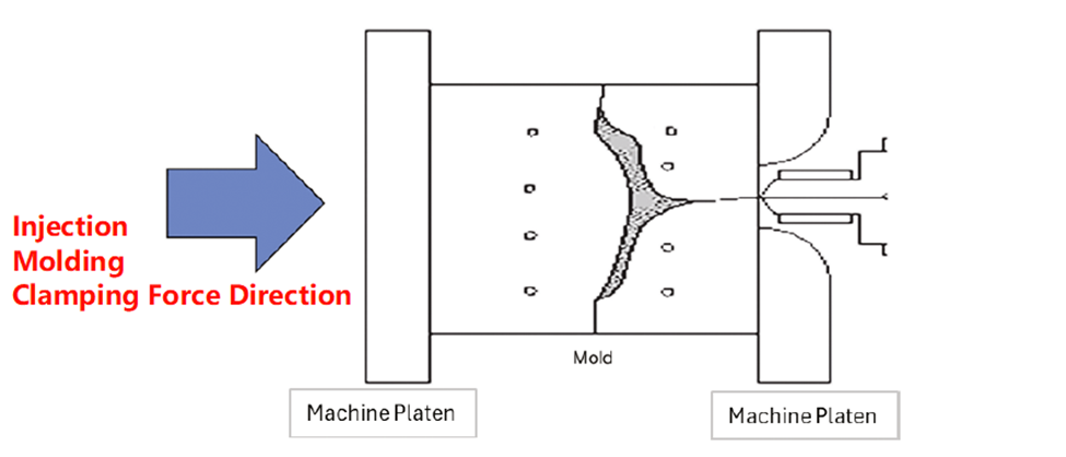
Supplier capacity should also be checked against real machine requirements. Clamp force alone does not determine whether a molding machine is suitable. Shot capacity, screw diameter, tie-bar spacing, platen dimensions, mold height, injection pressure, material residence time, robot access, hot-runner connections, and auxiliary equipment can restrict machine choice.
A 300-ton machine is not automatically better than a 200-ton machine for the same component. Oversized equipment can create unnecessary operating cost or unsuitable shot utilization, while undersized equipment may not provide enough clamp force or injection capacity. Machine selection should come from projected area, cavity count, resin behavior, mold dimensions, and shot size.
Supply continuity then depends on what happens when the preferred machine is unavailable. For a program consuming 20,000 components per week, several days of machine or mold downtime can affect assembly schedules. Qualified backup equipment, spare wear components, preventive maintenance records, approved resin sources, and realistic safety-stock agreements are more useful than verbal assurances about capacity.
Engineering communication closes the gap between all of these areas. When a trial part has 0.6 mm of warpage against a 0.3 mm requirement, the supplier should be able to discuss gate location, cooling balance, packing, resin orientation, geometry, and measurement method rather than changing machine settings without a defined test plan.
The same approach applies to mold trials. T0, T1, or later sampling stages should produce documented observations: cavity filling, flash, short shots, sink, weld lines, ejection marks, dimensions, part weight, cycle time, and proposed tool changes. If 30 samples are measured, the report should state which cavity produced each sample when cavity-to-cavity variation matters.
Buyers can test supplier capability with practical questions before issuing a purchase order:
-
Ask who performs DFM and whether feedback is based on the supplied resin grade and annual volume.
-
Request sample dimensional reports from comparable molded parts.
-
Confirm how many machines can run the intended mold and which one is planned for production.
-
Ask how material lots, cavities, production dates, and inspection records are identified.
-
Review what happens after a mold reaches 100,000, 500,000, or 1 million cycles.
-
Confirm who approves resin, tooling, machine, or process changes after production approval.
-
Check whether secondary operations are performed internally or by outside suppliers.
A supplier able to answer those questions with drawings, records, measurement methods, maintenance history, process sheets, and actual equipment information offers more manufacturing visibility than one relying mainly on a low piece-price quotation.